
|
|
| | Home | Products | Tools | Downloads | Contacts | | |
|---|---|
MOSFETs are often use in high power applications if high efficiency is needed. But the using of hight-end MOSFETs only does not guarantee the results. For this reason it is very important to estimate parameters of system, find an optimal balance and make a right chose of components.
There are enough publications and calculation examples for MOSFETs with different complexity and level of detail. Here is shown compact simplified calculation path with good accuracy.
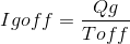
The MOSFEs power losses can be divided in conduction, switching and gate charging losses. The quiescent (leakage) losses are typically not significant for high power applications.
Conduction losses are determinate by Rds parameter and can be calculated as:

Switching losses has two components. The first one is losses due transition between on and off state:

The second component is a power to charge output capacitance:

Additional the power losses on reverse recovery diode can be calculated. It is reasonable to consider these losses only at higher switching frequencies because Qrr value is typically low:

The power to charge a gate can be calculated using total gate charge parameter:

Total MOSFET losses:

Note: In real systems the switch loses can be bigger as conduction losses. And low Rds parameter by choosing of transistor does not guarantee the optimal solution!
The gate control is a next impotent aspect. The rise and fail times of gate control must be less then rise and fall times of MOSFET specified in data sheet. Only in this case circuit will have minimal possible switching losses. To achieve this it is necessary to charge and discharge the gate capacitor with a corresponding current.

The gate capacitance is dynamical value and depends on gate driving voltage. Big value of Cg causes increasing of gate charge times and is important for choosing of gate driver. It can be simplified calculated using:

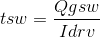
Real switching time can be calculated known driver current Idrv by:
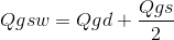
Qgsw can be found in MOSFET data sheet. If not, it can be approximated evaluated as:
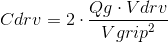
The capacitor across driver's power path Cdrv must be used for minimization of gate ripple voltage Vgrip:
Note: Because of the higher capacities required for power path, charge pump based drivers cannot be used instead of DC/DC converters (especially in high power applications or for the control of MOSFETs with high values of Qg).
In power inverter design often multiple parallel connected MOSFETs are used. This technique minimize the conductive loses, but increase the gate losses caused increasing total gate capacitance. The switching loses will be distributed between all transistors and first approach stay the same.
The maximal number of parallel connected transistors can be estimated from equation:
The gate driver must have specified peak current bigger as desired gate current Igon and Igoff. Following conditions must be met:


Otherwise, the driver will limit a performance of MOSFETs.
Note: The increased gate capacitance is another negative effect of multiple connected transistors. It means, that driver must be able to charge and discharge the total gate capacitance in shortest time. Otherwise increasing of the charge and discharge times will be cause an increasing of switching losses.
Here is an example of power inverter design for FOC of 3 phase motor.
Average system voltage: Vpwr = 48V
Maximal system voltage: Vpwr = 84V
Switching frequency: fsw = 20kHz
Average load current: Iload = 30A
Best way for fast and right choosing is a using of Product Selection Guide or Benchmark direct from manufacturer. According with system parameters three MOSFETs (with minimal Rds, with minimal Qg, and compromise between both) were selected for this design.
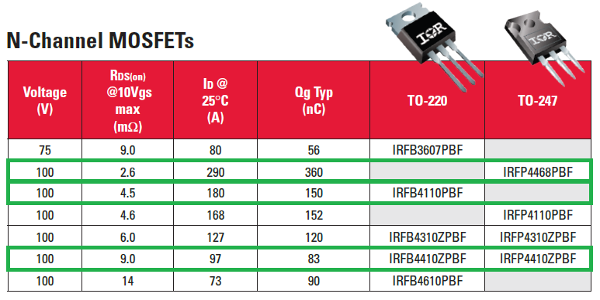
At this step power losses, desired gate driver current and gate capacitance for all selected MOSFETs must be calculated and analyzed.
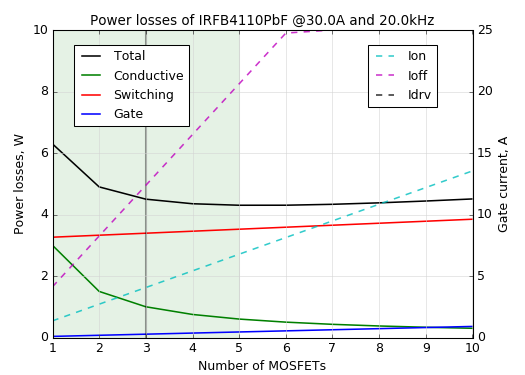
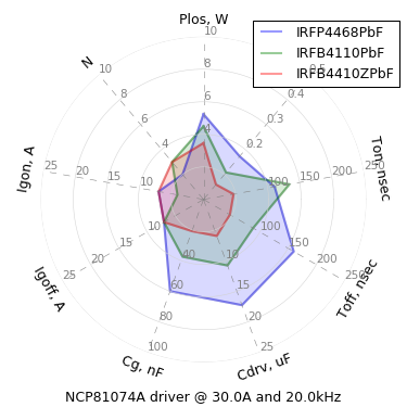
Here are radar chart of all MOSFETS with ideal gate driver limited on 25A and power losses of IRFB4110 dependent on number of parallel connected MOSFETs:
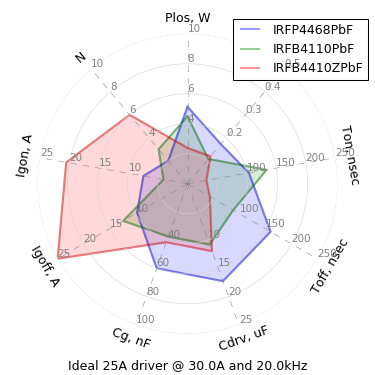
As can be seen in radar chart six parallel IRFB4410ZPbF (with minimal total gate charge) will have minimal power losses but need more than 20A (peak current) for gate drive.
The high current gate drives such as NCP81074A, UCC27322 or TC4422 have typically peak current capability up to 10A and cannot be used for driving such circuits. In this situation, it is only possible to develop own gate driver on discreet components with correspondent characteristics or try to optimize the system to existing one.
Here are radar charts of same MOSFET types with various real gate drivers
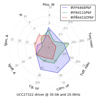
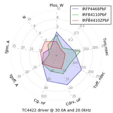
The both systems with UCC27322 and TC4422 MOSFET gate drivers have lower power loss values. But only TC4422 is explicitly specified in datasheet for capacitive load of 47,000pF. For this reason TC4422 can be better choice.
Driver voltage: Vdrv = 12V
Gate voltage ripple: Vrip = 1V
Gate power losses: Pgate = 0.07968W
MOSFET losses: Pmosfet = 3.0841632W
MOSFET: IRFB4410ZPbF (4x parallel connected)
MOSFET gate driver: TC4422
Power path capacitor: Cdrv = 7.968uF -> 10uF
Gate driver external resistor, high: Rh = 3.23hm -> 3R3
Gate driver external resistor, low: Rl = 3.73hm -> 3R9
The calculation Python script for MOSFETs can be found here: mosfet.zip
MD5 checksum: 425dd495f029b5408bd236aab88061a7